
3D Printer Fan Shroud
Design
•
Engineering
11
–
30,
2018
Over the summer of 2018, I worked at the 3D printing startup Create Orthotics & Prosthetics. I initially helped assemble and quality-check our large-format 3D printers, but I took on a design project towards the end of the summer: we needed faster, more even cooling around the nozzles.
About the Printers
The large-format 3D printers made by Create O&P were designed to quickly manufacture parts for the socket of a prosthetic device—that is, the part that interfaces with the amputee's residual limb. The printed parts included cosmetic outer shells, molds for silicone socket liners, and hard sockets for fit testing before a stronger permanent socket was made. All of these parts, particularly the test sockets, needed to be printable as single pieces within one or two hours.
As such, the printers were designed to have large, height-focused build volumes, enough to fit an entire upper or lower leg. They used large nozzles (0.8mm to 1 mm) to extrude plastic quickly and maximize strength. In the figure below, you can get a sense of the scale of these machines.


A Create O&P model 5400 3D printer, modified for R&D purposes. Left: overall view, with filament box tilted back. Right: a cosmetic leg cover printing in TPU.
Design Requirements
With the high flow rates of hot plastic that these printers achieved, the biggest challenge was cooling the deposited plastic below its glass transition temperature as quickly and evenly as possible. The fans we had been using blew air in the general direction of the nozzle, but now we needed to focus the air directly at the nozzle. This meant we'd need to design a duct.
The basic requirements for the duct were:
It had to provide a steady flow of air to all areas around the nozzle, as uniformly as possible.
It had to use air from a single blower fan, since adding additional fans would require upgrades to the printer's electronics that were out of the scope of this project.
Existing Design
The existing fan shroud encircled the hotend, but it failed to focus the airflow directly at the nozzle (see the figure below).

The existing fan shroud design when I joined the project. Note the wide opening that fails to force the air to the side opposite the blower fan.
My Designs
I created a duct with a large manifold but a small slit around the hotend. This design allowed pressure to build up within the manifold and forced the air through a smaller gap, achieving a few important outcomes:
The air would be focused more directly towards the nozzle.
The air would be accelerated by the small opening, increasing heat dissipation.
The air would exit the shroud more uniformly around the circle, so parts would be cooled more evenly.
Version 1
This version took inspiration from bladeless fans, and its geometry is shown below. The idea was to create a jet of air that would pull more air from around the nozzle, thereby increasing the overall flow.
When we tested this design, however, we found the following problems:
The extra airflow around the hotend resulted in difficulty keeping the temperature high enough.
More air came out of the near side than the far side.
There was no easy way to mount the blower fan to this shroud besides a friction fit.
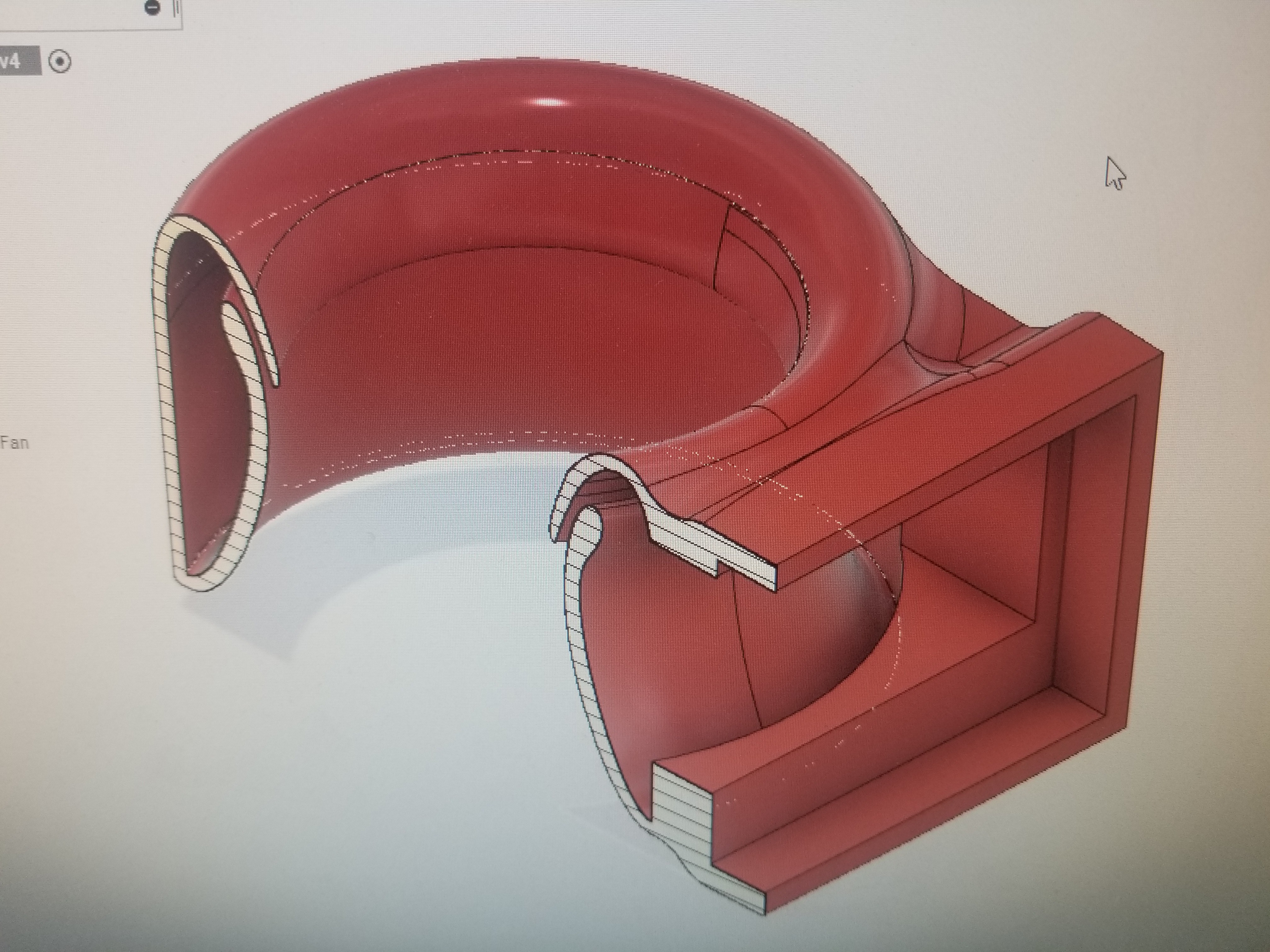
Cross-section view of Version 1 of my fan shroud design.
Version 2
This version addressed the problems in Version 1 in the following ways:
I abandoned the bladeless-fan-like design in favor of a nozzle exit at the bottom of the duct, as close as possible to the printbed. This removed the problematic airflow that was cooling the hotend rather than the part.
I increased the size of the manifold, decreased the thickness of the nozzle slit, and lengthened the path for the nozzle slit. This improved the evenness of the flow around the nozzle.
I added some plates with mounting holes, providing an easy mount point for the blower fan.

Cross-section view of version 2 of my fan shroud design. Note: the model is shown upside down, since it was designed to be 3D printed in this orientation. When the duct is installed on a printer, the nozzle ring faces downward.
The final product came together nicely!


The final product. Left: a top view, in the orientation that would be found when installed on a printer. Right: a bottom view, showcasing the nozzle ring.
